General arrangement of blocks
In total, this model has 5 main blocks with fuses and relays, and individual elements can also be installed outside them.
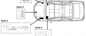
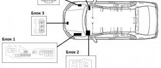
General scheme
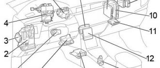
Location of blocks in the cabin for right-hand drive cars
Description
- heater relay
- mounting block under the instrument panel
- additional mounting blocks
- electric power steering control unit
- VSC system buzzer
- mounting blocks No. 7, No. 11
- turn signal switch relay
- accessory relay block
- SRS control unit
- engine and automatic transmission control unit
- control unit ABS, TRC, VSC, BA
Instructions for replacing fuses
Before replacing the fuse, it is necessary to establish the cause of the burnout of the protective element and eliminate it. As a rule, a short circuit, a break in the electrical wiring, or a power surge causes a fuse to burn out.
Fuse replacement pliers
To replace a blown fuse, specialized pliers are used. Their use allows you to grab the Toyota Corolla E120 fuse and pull it out of the seat. It is not always possible to perform this operation manually.
Replacement of fuses must be carried out in compliance with the following safety rules:
perform the operation with the battery terminals disconnected;
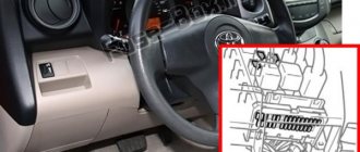
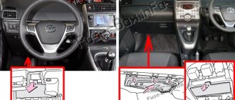
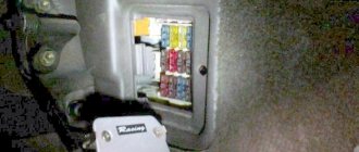
Blocks in the interior of Toyota Corolla E120 (Filder)
Main unit
In the general diagram it is designated as Block 2. In the cabin it is located under the panel on the left side.
Right hand drive
To gain access, you need to unscrew the screw, disconnect the fasteners and remove the glove compartment.
Example location
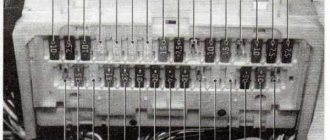
Photo example
Designation
Scheme
Full assignment of elements
| A | POWER 30A electric window lifts, electric sunroof |
| b | DEFOG 30A rear window defroster |
| With | HEATER 40A air conditioner, heater. |
| 1 | WASH 15A windshield wipers and washers |
| 2 | ECU-KZ 10A ABS, electric power steering, radiator and condenser fans |
| 3 | GAUGE 10A instrument cluster, turn signals and hazard warning lights, seat belt and key forgotten warning systems, central locking |
| 4 | backup circuit |
| 5 | backup circuit |
| 6 | backup circuit |
| 7 | WIPER 25A windshield wipers and washers |
| 8 | TAIL 15A dimensions and lighting, rear fog lamp, headlight warning system, headlights |
| 9 | STOP 15A brake lights, engine management, automatic transmission and ABS indicators |
| 10 | DOOR 25A central locking, interior lighting, warning system, wireless central locking control |
| 11 | P/W 20A - electric window lifts |
| 12 | Reserve |
| 13 | AM1 25A circuit AM1 ignition switch |
| 14 | ECU-B 7.5A fog lights, engine control and automatic transmission |
| 15 | FOG 15A front fog lights |
| 16 | ST 7.5A instrument cluster, engine management, starting system |
| 17 | A/C 25A air conditioner |
| 18 | IG2 15A ABS, charging system, automatic transmission, electric power steering, engine management, ignition, SRS |
| 19 | DEF I-UP 10A Engine Control, Rear Window Defogger |
| 20 | Reserve |
| 21 | CIG 15A cigarette lighter, radio, navigation system, clock, mirror adjustment |
Some relays are attached to the reverse side.
Photo diagram
Relay purpose and diagram
| A | Ignition relay |
| IN | Rear window defroster relay |
| WITH | Fuel pump relay |
| D | Electric window lift relay |
| E | Starter relay |
Left hand drive
To gain access you need to remove the glove box.
Example of assignment from the glove box lid
Scheme
Description
| 1 | not used |
| 2 | not used |
| 3 | not used |
| 4 | 25A FUEL HTR Fuel heater |
| 5 | 15A CIG Cigarette lighter, audio system, clock, controls for electric rear-view mirrors |
| 6 | 15A IG2 Sensors and counters, SRS air bag system, multi-channel fuel injection system/sequential multi-channel fuel injection system, starter system, charging system |
| 7 | 10A M-НТR/ DEF I-UP Anti-fog of external rear-view mirrors, multi-channel fuel injection system/ sequential multi-channel fuel injection system |
| 8 | 7.5A ST Starter, multi-port fuel injection system/sequential multi-port fuel injection system, sensors and counters |
| 9 | 10A ECU-B Air conditioning system, anti-lock brake system, vehicle stability control system, rear fog lamp |
| 10 | 25A AM1 Fuse “CIG” |
| 11 | 15A TAIL Dimensions, Taillights, License Plate Lights, Parking Lights, Headlight Beam Control, Instrument Panel Lights, Clock, Headlight Cleaner, Front Fog Lights, Seat Heaters, Multiport Fuel Injection System/Sequential Multiport Injection System |
| 12 | 20A P/V Electric drive window |
| 13 | 15A STOR Brake lights, high mounted brake light, gear lock control system, multi-port fuel injection system/sequential multi-port fuel injection system, anti-lock brake system, vehicle stability control system |
| 14 | 15A FOG Front fog lights |
| 15 | 25A DOOR Electric door locking system |
| 16 | not used |
| 17 | 10A A/C Air conditioning system |
| 18 | 7.5A OVD On-board diagnostic system |
| 19 | 10A GAUGE Sensors and meters, air conditioning system, power windows, reverse signals, daytime running lights, rear window defogger, automatic transmission overdrive system, power door locking system, charging system, hazard warning lights, automatic anti-glare interior rear view mirror, SRS airbag system, front passenger seat belt indicator light |
| 20 | 15A S-НТR Seat heaters |
| 21 | 15A WASH Windshield wipers and windshield washer |
| 22 | 10A ECU-IG SRS air bag system, electric cooling fan, anti-lock brake system, gear lock control system, electric steering system, headlight cleaner |
| 23 | 25A WIPER Windshield wipers and windshield washer, windshield wipers and rear window washer |
| 24 | 40A DEFOG Anti-fog rear window, fuse “M-HTR/DEF I-UP” |
| 25 | 30A POWER Electric drive window, electric sunroof |
| 26 | 40A HEATER Air conditioning system, fuse “A/C” |
Relay diagram on the back of the block
Designation
| A | Ignition relay |
| B | Rear window defroster relay |
| C | Fuel pump relay |
| D | Electric window lift relay |
| E | Starter relay |
| F | Electric window lifts, electric sunroof |
| G | Rear window defroster, air conditioning, heater |
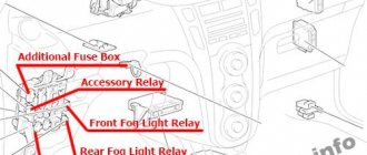
Additional relay block
In the general diagram it is designated as Block 5 In the cabin, located under the panel on the right side.
Scheme
Purpose
| A | Idle speed control system relay |
| B | Fog light relay |
| C | Relay for accessories |
| D | Heater relay |
Video
Fuses and relays are an integral part of any modern car, including the Toyota Corolla 120. Without fuses in the on-board electronics, the car would be akin to an open fire, nothing less.
The main task of fuses is to prevent the breakdown of any unit in the car and prevent the threat of fire in the vehicle's electrical wiring.
Very often, on “aged” cars, drowned cars, or simply on those cars that were used in poor conditions (high humidity or dryness, snow, etc.), the electrical wiring fails.
True, in such a situation there is one important nuance - the wiring consists of a large number of wires (engine, interior, so-called “braids”) and all of it cannot “break” immediately. It is this nuance that causes a lot of headaches for car owners when, despite all the working units, something suddenly stops working or, even worse, the insulation on the wires begins to melt.
It is worth paying special attention to the car’s electronics and not putting off potential repairs for a long time, because neglecting timely maintenance can cost you dearly!
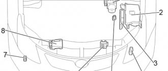
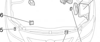
Blocks under the hood
Mounting block
In the general diagram it is designated as Block 1. It is located on the left side, next to the battery.
Example of a circuit from a block cover
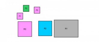
Scheme
Decoding
| A | Electric power steering relay |
| IN | Air conditioning compressor clutch e/m relay |
| WITH | Horn relay |
| D | Injection relay |
| E | Radiator fan relay #2 |
| F | Radiator fan relay #1 |
| A | EMPS (50A) - electric power steering |
| b | HEAD MAIN (40A) - headlights |
| With | A/PUMP (50A) - engine control (2ZZ-GE) |
| d | ALT (100A) charging system, rear window defroster |
| e | H-LP CLN (30A) – headlight washer |
| f | RDI FAN (30A) - radiator and condenser fans |
| g | ABS No. 1 (30A) or VSC No. 1 (40A) - ABS |
| h | ABS No. 2 (40A) or VSC No. 2 (40A) - ABS |
| 1 | HEAD RH (15A) - right headlight |
| 2 | HEAD LH (15A) - left headlight |
| 3 | HORN (10A) - sound signal |
| 4 | HAZARD (10A) - direction indicators and hazard warning lights |
| 5 | ALT-S (5A) - charging system |
| B | spare |
| 7 | EFI (15A) engine management, automatic transmission operating mode indicators, headlights, interior lighting, automatic air conditioning, radio, headlight warning system, remote central locking, ABS (VSC) |
| 8 | DOME (15A) clock, instrument cluster, headlights, interior lighting, air conditioning with automatic control, radio, warning system, lights not turned off, remote control |
| 9 | AM2 (30A) - circuit AM2 ignition switch |
| 10 | backup circuit |
| 11 | backup circuit |
| 12 | backup circuit |
| 12 | backup circuit |
Block 3
Installed next to radiators and cooling fans.
Scheme
Description
- Radiator fan relay #1
- Radiator fan relay #2
- Radiator fan relay #3
Block 4
Can be installed on the right side of the engine space.