Toyota Funcargo passenger van of the 1st generation, produced in 1999, 2000, 2001, 2002, 2003, 2004, 2006, 2007. In European countries it was sold under the name Toyota Yaris Verso or Verso-S (Verso-S). In this article you can find information describing the locations of electronic control units, the purpose of fuses and relays of Toyota Funcargo with block diagrams and photo examples of their location. Let's highlight the cigarette lighter fuse. This material will also be useful to owners of Toyota bB and Scion xB, since these cars have similar electrical circuits.
The location of the blocks and their design may differ from those presented and depend on the region of delivery and the year of manufacture of your car.
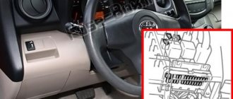
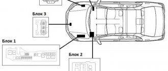
Fuse box location
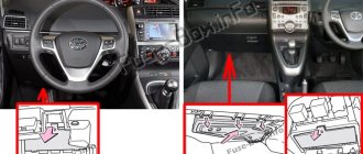
Passenger compartment
It is located behind the cover on the left side of the dashboard.
Engine compartment
The fuse box is located next to the battery.
Front compartment
There are two fuse boxes - one to the right of the trunk compartment, the other under the trunk trim.
Code meaning
If the diagnostic conclusion is error code 21, then your “iron friend” has problems with the oxygen sensor (or Lambda Probe). This part is very important for your car, because it is responsible for maintaining the optimal ratio of air and fuel entering the cylinder of the engine system. 14.7:1 - these indicators are considered the most successful in the ratio of air and fuel. In modern engine models, the lambda probe is installed in at least two places: before the catalyst and after. In this case, the most accurate information is sent to the electronic unit. In the diagnostic report, Toyota error 21 looks like this: “OBD 2 this = error P0135 O2 Sensor Heater Circuit Malfunction (Bank 1 Sensor 1)=”
The essence of the problem lies in the malfunction of the oxygen sensor heater, which results in overheating of the catalyst. The service life of an oxygen sensor in our harsh conditions is relatively short, only about 2 years. In addition to the conditions in which the car is operated, the service life can also be affected by the technical condition of the engine.
Fuse Box Diagrams
Fuse box in the passenger compartment
Assignment of fuses in the instrument panel
| № | Name | ampere | Description |
| 9 | WASHER | 10A | Windshield wiper and washer |
| 10 | HTR | 10A | Air conditioner |
| 11 | WIPER | 20A | Windshield wiper and washer |
| 12 | ECU-IG | 7.5A | Power steering system, anti-lock braking system |
| 13 | FAN-IG | 7.5A | Electric cooling fans |
| 14 | TURN | 7.5A | Turn signals, hazard flashers |
| 15 | SENSOR | 7.5A | Power window system, sensors and meters, reversing lights, charging system, rear window defogger system |
| 16 | SRS | 7.5A | SRS airbag system |
| 17 | DEF | 25A | Heated rear window |
| 18 | OBD | 7.5A | On-board diagnostic system |
| 19 | AM1 | 7.5A | Fuses “GAUGE”, “ACC”, “TURN”, “ECU-IG”, “WIPER”, “WASHER”, “SRS”, “HTR 10A”, “FAN-IG” |
| 20 | ACC | 25A | Fuses “RADIO2”, “SIG” |
| 21 | DOOR | 15A | Power door lock system |
| 22 | FR FOG | 15A | Front fog lamp |
| 23 | STOP | 15A | Brake lights, high brake light, sequential manual transmission |
| 24 | TAIL | 20A | Fuses “TAIL2”, “PANEL” |
| 25 | DP/W | 20A | Window lift system |
| 26 | PP/W | 20A | Window lift system |
| 27 | Radio1 | 15A | Power antenna, radio |
| 28 | DOME | 10A | Watch |
| 29 | BUD-B | 10A | Daytime running light system, sensors and meters |
| 30 | TAIL2 | 10A | Tail lights, parking lights, license plate lights, gauges and meters |
| 31 | PANEL | 7.5A | Clock, backlight |
| 32 | Radio2 | 7.5A | Sensors and meters, exterior mirror system, clock |
| 33 | C.I.G. | 15A | Lighter |
| 34 | I/UP | 7.5A | Engine idle system |
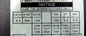
Fuse box in the engine compartment
Assignment of fuses in the engine compartment
| № | Name | ampere | Description |
| 35 | ALT-S | 7.5A | Charging system |
| 36 | ECU-B1 | 25A | Fuses “ECU-B”, “DOME” |
| 37 | SMT-B | 10A | 1999–2001: not used; 2002-2007: Sequential manual transmission system |
| 38 | HORN | 10A | horn |
| 39 | HAZ | 15A | Turn signals, hazard flashers |
| 40 | AM2 | 15A | Starter System, Multiport Fuel Injection System/Sequential Multiport Fuel Injection System, SRS Airbag System |
| 41 | IG2 | 15A | Ignition system, multiport fuel injection system/sequential multiport fuel injection system |
| 42 | EFI1 | 15A | Multiport fuel injection system/sequential multiport fuel injection system, engine immobilizer system |
| 43 | ETCS | 15A | 1999–2001: not used; 2002-2007: Multiport fuel injection system/sequential multiport fuel injection system. |
| 44 | HPU | 30A | 1999–2001: not used; 2002-2007: Sequential manual transmission system |
| 45 | DRL No. 1 | 7.5A | 1999-2002: Daytime running light system. |
| 45 | HEAD RIGHT LWR | 10A | 2003-2007: Right headlight (low beam). |
| 46 | DRL No. 2 | 20A | 1999-2002: fuses “HEAD LH LWR”, “HEAD RH LWR”, “HEAD LH UPR”, “HEAD RH UPR” |
| 46 | HEAD LH LWR | 10A | 2003-2007: Left headlight (low beam). |
| 47 | EFI2 | 7.5A | Multiport fuel injection system/sequential multiport fuel injection system |
| 48 | ST | 7.5A | Starter system |
| 49 | SMT-IG | 10A | 1999–2001: not used; 2002-2007: Sequential manual transmission system |
| 50 | DRL No. 1 | 7.5A | 1999–2002: not used; 2003-2007: Daytime running light system. |
| 53 | BASIC | 40A | 1999-2002: Starter system, fuses “DRL”, “DRL No. 2”; 2003-2007: Starter system, fuses “DRL NO.1”, “HEAD LH LWR”, “HEAD RH LWR” |
| 54 | HTR | 40A | Air conditioner |
| 55 | ALT | 100A | Fuses "AM1", "DP/W", "PP/W", "DOOR", "STOP", "EHPS", "DEF", "TAIL1", "OBD", "HTR 40A" |
Fuse boxes in luggage compartment
Assignment of fuses in the trunk
| № | Name | ampere | Description |
| 1 | – | 30A | Spare fuse |
| 2 | – | 15A | Spare fuse |
| 3 | – | 20A | Spare fuse |
| 4 | RDI FAN | 30A | Electric cooling fans |
| 5 | ABS1 | 20A/30A | Anti-lock braking system (1999-2002 – 20A; 2003-2007 – 30A) |
| 6 | CDS FAN | 30A | Electric cooling fans |
| 7 | LH UPR HEAD | 10A | Left headlight (high beam) |
| 8 | HEAD UPPER RIGHT | 10A | Right headlight (high beam) |
| 7a | HEAD LH LWR | 10A | 1999-2002: Left headlight (low beam); 2003-2007: Not used |
| 8a | HEAD RIGHT LWR | 10A | 1999-2002: Right headlight (low beam); 2003-2007: Not used |
| 51 | ABS2 | 40A/50A | Anti-lock braking system (1999-2002 - 40A; 2003-2007 - 50A) |
| 52 | EHPS | 50A | Power steering system |
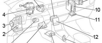
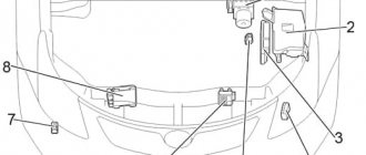
Blocks under the hood
Location
General layout of blocks under the hood
Purpose
- Power fuse block
- Additional fuse block
- Fuse and relay box
- ABS control unit
Power fuse block
It is located on the positive terminal of the battery and is made in the form of high power fuse links.
Scheme
Decoding
- 60A MAIN - Fuses: “EFI”, “DOME”, “HORN”, “ST”, “AM2”, “H−LP LH”, “H−LP RH”, “H−LP LH (HI)”, “ H−LP RH (HI)”, “H−LP LH (LO)”, “H−LP RH (LO)”
- 80A - “START/STOP” system
- ALT 100/120A - Fuses: “ECU-B”, “TAIL”, “D/L”, “OBD”, “RDI”, “AM1”, “HAZ”, “HTR”, “HTR-SUB1”, “ POWER”, “STOP”, “DEF”, Charging system
- 60A ABS - ABS
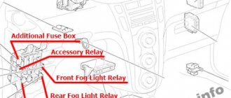
Additional block
Scheme
Description
| 1 | 10A H-LP HI RH - Headlights (daytime running lights) |
| 2 | 10A H-LP HI LH - Instrument cluster, headlights (daytime running lights) |
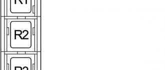
| Relay | |
| R1 | Headlights |
| R2 | Dimmer (DIM) |
| R3 | — |
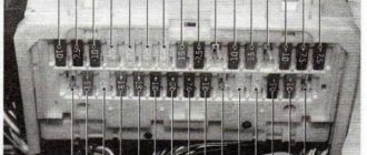
Fuse and relay box
This unit is located on the left side of the engine compartment, next to the battery.
Photo
Scheme
Designation
| 1 | 15A DOME - Clock, instrument cluster, dual locking, headlights, interior lighting, warning buzzer, multi-information display, audio system, door lock control unit |
| 2 | 15A EFI - Engine control module, immobilizer, transmission control module |
| 3 | 15A HORN - Horn |
| 4 | 15A AM2 - Charging system, instrument cluster, engine control unit, immobilizer, transmission control unit, multi-information display, SRS airbag system, ignition system |
| 5 | 30A ST - Starting system |
| 6 | — |
| 7 | 10A H−LP LH - Left headlight, headlight range control |
| 8 | 10A H−LP RH - Left headlight, headlight range control |
| 9 | 15A P/POINT - Outlet |
| 10 | Spare fuse |
| 11 | Spare fuse |
| 12 | Spare fuse |
| 13 | — |
| 14 | — |
| 15 | 30A RDI - Cooling Fan |
| 16 | 50A HTR SUB1 - Auxiliary heater (PTC) |
| 17 | — |
| Relay | |
| R1 | Cooling fan |
| R2 | Cooling fan |
| R3 | Starter |
| R4 | — |
| R5 | Socket |
| R6 | Auxiliary heater (PTC) |
| R7 | EFI |
| R8 | A/C compressor clutch |
| R9 | Sound signal |
What to do if error code 21 is detected
New lambda probe for 1JZ-GE If a problem is identified, it will have to be eliminated solely by replacing the sensor. All that remains is to decide which device to buy: the original or a replacement. Of course, the original part will cost many times more. Before purchasing, you must also find out the catalog number of the original oxygen sensor. On the body of a faulty oxygen sensor its unique number is indicated, but if you do not want to dismantle the part before purchasing, then it is quite possible to find the article number on the Internet. To do this, it is worth studying the offers from online auto parts stores. To search, you will need to enter the VIN code or body number of your car. If you have a desire to supply not the original part, but a substitute, then the online store will help you in this case too. Most often, the catalog article number (number) of the replacement is located next to the original. There are also models of universal sensors. The simplest and most correct way would be to go straight to a car dealership or car service center, where your problem will be solved for you in the best possible way.
The most common 5 reasons for the error
The most common problems when this error occurs are:
- Oxygen sensor malfunction;
- The fuel filler cap is not tightly closed;
- Failure of the exhaust gas catalyst;
- Malfunction of the mass air flow sensor;
- Faulty spark plugs or high-voltage wires.
Let's look at each of the reasons in a little more detail. The oxygen sensor is part of the system that processes exhaust gases. This sensor helps control fuel consumption.
A malfunction of this sensor is taken as an engine malfunction. That is, the system cannot accurately calculate the fuel supply level and this is precisely why the error occurs.
Most Corolla models have from 2 to 4 such sensors, so we should know that an error due to them is possible.
The next option is a loosely sealed fuel tank. On the tank neck of any modern car there is a sensor that is responsible for the tightness of its closure. So if the neck is not closed tightly, the car's computer accepts this as an engine error. Therefore, before suffering from a malfunction, it is worth checking the cover.
The third option may be an exhaust gas catalyst. When it becomes unusable, the car's engine loses its power and due to this, the car's computer may also show an error, since loss of power is a good reason for turning on the error. Loss means some kind of malfunction.
The air flow sensor regulates the amount of air supplied to the fuel for further launch into the engine cylinders. A faulty air supply sensor can lead to an increase in fuel consumption, as well as a decrease in engine power, so the on-board computer may consider this malfunction as an engine error.
Failed spark plugs can also be one of the causes of engine malfunction. The process of incorrect ignition in the engine cylinders usually leads to an error that is generated by the computer. Replacing the spark plugs or adjusting them can correct the problem and eliminate the computer error.
These are the main reasons why the “Check engine” or “Check engine” error appears on a Toyota Corolla. However, to more accurately clarify the problem, we can use self-diagnosis.
Self-diagnosis of the “Check engine” error on a Toyota Corolla
Self-diagnosis is a simple and very fast way to eliminate errors and find their causes. To carry it out, we will need a smartphone - in our case, a Samsung phone running on Android.
We will also need OVD2-VT - this is a special adapter that, through a wireless connection to the phone, allows you to decipher and eliminate error codes. All this pleasure will cost you 1000 rubles.
This is how much the adapter costs, which plugs directly into the diagnostic connector located under the dashboard on the driver’s side.
So we have a broken down car, we bought an ELM and we have a phone. What's next? And then we need to configure our equipment. You should start by installing the software on your phone. We will use a program such as “Torque. By its name, you can easily find it on the Android Market, download it there and install it on your mobile device.
In fact, there are a huge number of similar programs in this application store, but we chose this one due to its convenience. This program can be completely customized for yourself.
Setting up indicators that will be displayed during diagnostics, the ability to decipher stakes and reset errors - all this is available in this application. The program is simple and has a nice user interface. The most difficult part of this program is filling in the data about the vehicle being tested.
By the way, it is worth noting that not only Corollas are suitable for testing, but also other cars, including makes and models.
Let's proceed directly to self-diagnosis. We have installed the program, after which we need to insert the adapter into a special diagnostic connector. In the photo shown below there is a special connector - it is highlighted in a red circle.
We place the phone on the stand, if one is available. Next we need to start the car and turn on Bluetooth on the phone.
After Bluetooth is turned on, launch the program on the phone. After a few minutes, the program will load and begin transferring data from the adapter to the phone. Which in turn will display engine parameters on the phone screen. The photo below shows the main working screen of the program.
In order for us to diagnose our engine and finally understand why the “Check Engine” light is on, we need to go from the main table to the appropriate section of the program, it is not difficult to recognize it, you can even do this by the engine icon.
By clicking on it, the program begins to automatically read the ECU memory. When scanning, errors are detected, if any, of course, which are displayed by indicating the codes and their descriptions.
After which, if you have access to the Internet, the program allows you to find out more information from the errors displayed and understand what actually is the cause of your malfunction. And finally, after you have figured out what the problem is, the program gives you the opportunity to erase all errors from memory.
After clearing the computer’s memory, the error disappears and the “Check” light stops lighting up on the dashboard and annoying you. Below this process is shown in pictures for greater convenience.
So, the process of checking the engine of your car is completed, you know its reason and can confidently repair the unit that has become faulty. And the light bulb completely stops burning.
In general, an excellent program for solving similar problems with the engine.
However, it is disappointing that using such an adapter you can only diagnose the engine, that is, it will not be possible to diagnose the ABS or other components and systems of the car.
It is also worth knowing that resetting a lit light is not always possible, since it is possible that you actually have a serious engine malfunction. So the program can only show the malfunction, and it can reset the error only after repair, that is, after the cause of the error has actually been eliminated.
That's all. The question is quite nervous, but it also has its advantages. For example, the price of the issue, as well as the ability to independently find out the cause and eliminate it, if, of course, you understand your car. Good luck to everyone, and less problems with your pets.
Source: https://corollafan.ru/obsluzhivanie/prover-dvigatel-tojota-korolla.html
Symptoms of “disease code 21” in a Toyota engine
All deviations in the operation of the car as a result of the failure of the oxygen sensor can be divided into two types:
- As a result of increased fuel content/lack of air (rich mixture).
- As a result of increased air content/lack of fuel (lean mixture).
The very first and most obvious sign of error 21 is increased fuel consumption. Because as a result of a breakdown of the oxygen sensor, the electronic unit takes average readings of the air and fuel mixture.
In addition to increased fuel consumption, many other deviations can be observed, such as:
- reduction of dynamic capabilities;
- extraneous sounds in the gearbox;
- appearance of black smoke;
- decrease in the “sensitivity” of the car.
And this is not a complete list of troubles caused by the problem.