Toyota Karina E T190 (Crown) - fuses and relays
Toyota Carina E
represents the 6th generation of the
Carina
, which was produced in 1992, 1993, 1994, 1995, 1996, 1997 and 1998 with hatchback (liftback), sedan, and station wagon (wagon) bodies.
During this time, it underwent restyling. This model is the European version of the 9th generation left-hand drive Toyota Crown T190 . These cars are very similar, the key difference is the location of the steering. In this publication you can find a description of the fuses and relays of the Toyota Carina E (Crown T190) with block diagrams and their locations. Note the fuse responsible for the cigarette lighter.
The design of the blocks and the purpose of the elements in them may differ and depend on the region of delivery (Karina E or Corono T190), the level of electrical equipment, engine type and year of manufacture.
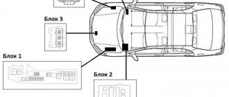
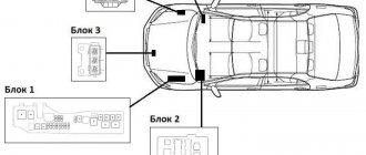
Block in the cabin
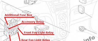
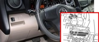
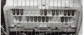
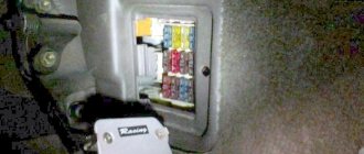
In the cabin, the main fuse box is located in the instrument panel behind a protective cover.
Photo - diagram
p, blockquote 7,0,0,0,0 —>
| A | 40A AM1 (ignition switch output circuit AM1 (terminals ACC. IG1. ST1) |
| b | 30A POWER (windows, sunroof and central locking) |
| With | 40A DEF (rear window defroster) |
| 1 | 15A STOP (brake lights) |
| 2 | 10A TAIL (dimensions) |
| 3 | 20A TAIL MAIN (dimensions) |
| 4 | 15A ECU-IG (transmission electronics. ABS, control system lock (automatic transmission) |
| 5 | 20A WIPER (windshield wipers) |
| 6 | 7.5A ST (starting system) |
| 7 | 7.5A IGN (ignition) |
| 8 | 15A CIG & RAD (cigarette lighter, radio, clock, antenna) |
| 9 | 10A TURN (turn signals) |
| 10 | 15A ECU-B (ABS, power supply for central locking) |
| 11 | 7.5A PANEL (instrument lighting, glove box lighting) |
| 12 | 30A FR DEF (rear window defroster) |
| 13 | 10A GAUGE (devices) |
| 14 | 20A SEAT HTR (seat heater) |
| 15 | 10A MIR HTR (mirror heater) |
| 16 | 20A FUEL HTR (fuel heater) |
| 17 | 15A FR DEF IAJP (increasing idle speed when the windshield heater is turned on) |
| 18 | 7.5A RR DEF 1/UP (increasing idle speed when turning on the rear window heater) |
| 19 | 15A FR FOG (fog lights) |
Fuse number 8 at 15A is responsible for the cigarette lighter.
'95 - '02 Toyota Corolla (E110) Fuse Diagram
RUBONOV
| No. | Fuse | A | Scheme |
| 1 | 7,5 | Turn signals, direction indicators | |
| 2 | – | – | – |
| 3 | SENSOR | 10 | Gauge and meters, reverse lights, air conditioning system, power windows, heated rear window, power door lock system |
| 4 | WIP | 20 | Windshield wipers and washer |
| 5 | I/UP | 10 | Multiport fuel injection system/sequential multiport fuel injection system, remote control mirror |
| DEF I - UP / M - HTR | 10 | Heated rear window, multiport fuel injection system/sequential multiport fuel injection system | |
| 6 | ECU-IG | 10 | Starting system, electric cooling fan, automatic transmission shift lock system, anti-lock braking system, cruise control |
| 7 | IGN | 7.5 | Multiport fuel injection system/sequential multiport fuel injection system, charging system, SRS airbag system, seat belt pretensioners |
| 8 | STOP | 15 | Brake lights, high brake light, anti-lock braking system, automatic transmission shift lock system |
| 9 | TAIL | 15 | Tail lights, gauges and instruments, instrument panel light control, cigarette lighter, clock, car audio system, rear window defogger, license plate light, electronically controlled automatic transmission system, multiport fuel injection system/sequential multiport fuel injection system, air conditioning system. alarms |
| 10 | – | – | – |
| 11 | – | – | – |
| 12 | DB | 7.5 | On-board diagnostic system |
| 13 | EBU-B | 7,5 | LHD: SRS airbag system, seat belt pretensioners, rear fog lamp |
| 5 | RHD: SRS airbag system, seat belt pretensioners, rear fog lamp | ||
| 14 | ST | 5 | Starter system, multiport fuel injection system/sequential multiport fuel injection system |
| 15 | D/L | 30 | Power door lock system |
| 16 | FOG | 15 | Fog lights |
| 17 | S-HTR | 15 | Seat heating |
| 18 | – | – | – |
| 19 | C.I.G. | 15 | Car audio system, clock, cigarette lighter , power mirrors, SRS airbag system, seat belt pretensioners, automatic transmission shift lock system, anti-theft system |
| 20 | – | – | – |
| 21 | Noise filter | – | "DOME" |
| 22 | DEF | 40 | LHD: Rear window defroster, "DEF I-UP/M-HTR" fuse |
| 30 | RHD: Rear window defroster, "DEF I-UP/M-HTR" fuse | ||
| 23 | POWER | 30 | Power windows, power sunroof |
| 24 | – | – | Pin short |
.
Blocks under the hood
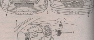
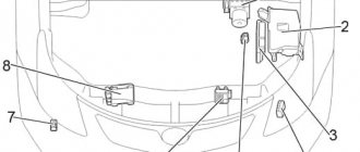
Several blocks with fuses and relays can be located in the engine compartment.
General layout of blocks
Designation
p, blockquote 12,0,0,0,0 —>
- 3 - main relay and fuse block
- 4 - relay block
- 5 - additional relay and fuse block
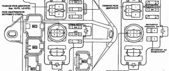
Main unit
Several options for its implementation are possible.
Option 1
p, blockquote 18,0,0,0,0 —>
| Circuit breakers | |
| A | 50A HTR (heater) |
| b | 40A MAIN (main fuse link) |
| With | 30A CDS (condenser fan) |
| d | 30A RDI (Air Conditioner Radiator Fan) |
| e | 100A ALT (charging) |
| f | 50A ABS (ABS) |
| 1 | 15A HEAD RH* (right headlight) |
| 2 | 15A HEAD LH* (left headlight) |
| 3 | 15A EFI (injection system) |
| 4 | spare |
| 5 | spare |
| 6 | 15A HAZARD |
| 7 | 10A HORN (horn) |
| 8 | — |
| 9 | 7.5A ALT SENCING (charging) |
| 10 | 20A DOME (electric drive and interior lighting) |
| 11 | 30A AM2 (Ignition switch circuit AM3, terminals IG2 ST2) |
| Relay | |
| A | STARTER - Starter |
| IN | HEATER - Heater |
| WITH | EFI MAIN - Injection system |
| D | ENGINE MAIN - Main relay |
| E | HEAD - Headlights |
| F | HORN - Signal |
| G | FAN No. 1 - Radiator fan |
Option 2
Decoding
p, blockquote 21,0,0,0,0 —>
| a | CDS (condenser fan) |
| b | RDI (radiator fan) |
| c | MAIN (main fuse link) |
| d | HTR (heater) |
| e | 100A ALT (charging) |
| f | 50A ABS (ABS) |
| 1 | |
| 2 | HEAD LH (left headlight) |
| 3 | HORN (horn) |
| 4 | |
| 5 | HEAD RH* (right headlight) |
| 6 | HAZARD (Hazard Alarm) |
| 7 | 7.5A ALT SENCING (charging) |
| 8 | 20A DOME (electric drive and interior lighting) |
| 9 | 30A AM2 (Ignition switch circuit AM3, terminals IG2 ST2) |
| Relay | |
| A | ENGINE MAIN - Main relay |
| IN | FAN No. 1 - Radiator fan |
| C | HEAD - Headlights |
| D | STARTER - Starter |
| E | HORN - Horn |
| F | HEATER - Heater |
Relay block
p, blockquote 24,0,0,0,0 —>
- A - A/C FAN No. 2 - Radiator fan relay
- B - A/C FAN No. 3 - Radiator fan relay
- C - A/C MG CLT - A/C Clutch
Relay block No. 5
In the general diagram it is indicated by number 2.
Scheme
Designation
- A - air conditioning compressor clutch e/m relay
- B - relay No. 3 of the electric motor of the cooling system fan
- C - relay No. 2 of the electric motor of the cooling system fan
- D - relay No. 1 of the electric motor of the cooling system fan
- E - power relay No. 2
- F - power relay No. 1
If you know how to make the material better, write in the comments.
Replacement
Sometimes situations arise when it is necessary to replace fuses or relays in any of the blocks of a Toyota Carina. Despite the reliability of a Japanese vehicle, a failure may occur in the electrical system, causing the element that is responsible for the safe operation of the vehicle's devices to overheat. This element is fuses or relays.
The presence of a fault in the fuse can only be determined visually, so you will have to open the block and find the required element. The main signs of a problem are darkening of the housing and the formation of part defects, presented in the form of broken connections.
Before making a replacement, there are a few tips to consider:
- Replacement must be done with tweezers. And it is desirable that it is not metal and small. This will not only ensure the safety of the person replacing the part, but will also preserve the integrity of the electrical systems and the fuse itself.
- The replacement part must be an analogue of the failed one. Most car enthusiasts carry a set of spare fuses and relays with them in their car. The diagram on the unit cover, as well as the numbering of the fuses in the unit itself, will help determine which element is needed.
- If the problem occurs in the fuses, then it must also be taken into account that the malfunction may also occur in the inserts.
To replace the fuse, you will first need to turn off the car's engine, as well as the battery in order to stop the flow of electrical current through the network. Once these steps are completed, you can begin to remove the unit cover and directly replace the faulty element.
Toyota Karina E is a car that has earned the trust of most car enthusiasts. The presence of three fuse and relay blocks indicates the safe operation of many functions and devices of the vehicle.
Instructions for replacing fuses Toyota Corona/Caldina
The proper functioning of many car parts directly depends on the condition of the fuses. If the headlights or other electrical components of the Toyota Corona/Caldina break down, the first thing you should check is these parts.
Fuse condition diagnostics
The fault can only be determined by direct inspection of the fuses. A malfunction will be indicated by obvious defects in parts, similar to a broken connection. If they are not there, but the element still raises suspicions, then it is best to replace it.
Recommendations from the manufacturer Toyota Corona/Caldina
Before moving on to the process of removing and installing new parts, you should learn the following tips from experts:
- to replace fuses designed for low currents, you need to use a special tool - a tweezers-type puller;
- It is worth ensuring that the new part fully matches the used one in order to avoid serious damage and even fire;
- Before solving a problem with fuses, you should pay attention to the fuses, which may also be the cause of the malfunction.
In order to quickly carry out a replacement, it is worth being safe. By purchasing a set of spare fuses, you can quickly stop the malfunction right on the spot and continue on your way.
How to replace a damaged fuse?
You can learn about the details of checking and replacing Toyota Corona/Caldina fuses from the special instructions prepared by the manufacturer. Pay attention to the illustrations and tabular data. They are very important in order not to make mistakes when removing and installing parts.
Ask in the comments. We will definitely answer!
Refractory fuse diagram
The operating instructions provide detailed fuse location diagrams to make it easier to replace them yourself. If you do not know the reason why certain devices do not work, start looking for a blown fuse. We will show how to do this using the example of a radio, which often becomes a victim of incorrect use of capabilities. First you need to figure out where the Toyota Corolla radio fuse is located. Please note that the diagrams for the 2008 Corolla, Corolla 150, TOYOTA CORONA PREMIO, Echo and later Avensis, Rav 4 and Land Cruiser 100 models may be different.
Layout diagram
Fuse layout
What does the block to the left of the driver look like?
Block on the left side of the driver Instructions
Description of the Corolla fuse diagram (from the documentation)
The fuse box is located in the passenger compartment on the passenger side in the glove compartment. Very often it fails not because of a malfunction of the car, but because of an attempt to use the cigarette lighter for other purposes. Mainly as a power source. If the radio is playing at this moment, the auto fuse may burn out.
In some circuits (see above) you can find an additional fusible circuit breaker for the audio system; sometimes other elements of the electrical network fail, affecting the performance. So it’s better to get the final version of your block from the documentation for your model. The layout of the Corolla 2008, as well as the Corolla 150, Crown Premium, and Echo may differ. Especially in the latest models Avensis, Rav 4 and Land Cruiser 100.
For example, you can compare it with the Corona Premium scheme, issued before 2001. The required machine is located in the engine compartment at number 9, and the number of circuit elements is significantly less than in modern cars. The same story awaits you in the diagram of the Toyota Echo model.
Main unit
The main fuse and relay box is located under the hood of the car near the battery. The elements of this unit are responsible for the safe operation of electrical systems that provide important vehicle functions. For example, fuses regulate the flow of fuel to the pump and turn the windshield wipers on or off.
Below is a diagram of the location of fuses and relays in the block, as well as a table that shows the purpose of the main elements.
| Designation | Purpose |
| 1 | Ensuring the operation of the electronic engine control unit of a car |
| 2 | Adjusting the sound signal. |
| 3 | Ensuring the generator is operational. |
| 4 | Car interior lighting, as well as lighting for the trunk, clock, and dashboard. |
| 5,6 | Turning headlights on and off. |
| 7 | Organization of uninterrupted operation of the ignition switch. |
| Relay | |
| R1 | Fuel pump operation. |
| R2 | Starter activation relay. |
| R3 | Horn relay. |
Also, the fuses and relays of this unit are responsible for the cigarette lighter and provide electricity to the fan and the stove.
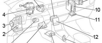
General scheme
General layout of electronic control units
Description
- right front SRS sensor
- relay block No. 5 (models before 12.1997)
- Manifold absolute pressure sensor (3S-FSE)
- Brake booster vacuum sensor (3S-FSE)
- intake manifold absolute pressure sensor (except 3S-FSE and diesel models)
- boost pressure sensor (diesel models)
- boost pressure sensor (absolute pressure in the intake manifold) (2С-Т)
- ABS control unit and modulator (models from 12/1997)
- injector control unit (from 12.1997)
- glow plug relay (diesel models)
- relay block No. 2
- mounting block in the engine compartment
- fuse block
- left front SRS sensor
- navigation system unit
- stereo system amplifier (models before 12.1997); TV tuner (models from 12/1997)
- injector control unit (models up to 12.1997)
- rear window wiper relay
- connector holder
- injector control unit relay (models up to 12.1997)
- fuel pump relay
- ABS control unit (models up to 12.1997)
- injector control relay (models from 12.1997)
- relay block No. 4
- relay "EFI-2" (models from 12.1997)
- electronic engine control unit
- door lock control relay
- integrated relay
- mirror defroster relay
- relay block No. 1
- connector mounting bracket
- mounting block in the cabin
- Front window defogger relay
- central mounting block
- ETCS relay
- relay "EFI-2" (models before 12.1997)
- automatic transmission selector relay
- central SRS sensor
- ABS deceleration sensor.
Fuses and relays Toyota Carina E (T190), 1992 - 1998
Most of the power supply circuits of the electrical equipment of the Japanese sedan and station wagon are protected by fuses.
Headlights, electric fan motors, fuel pump and other powerful current consumers are connected through a relay. The protective elements are installed in mounting blocks, which are located under the hood and in the trunk. The fuse diagrams are suitable for Toyota Carina E (T190) 6th generation 1992, 1993, 1994, 1995, 1996, 1997, 1998 vehicles with gasoline and diesel engines.
In the cabin
Component location. 1 - fuse block No. 3, 2 - fuse block No. 1.
| Number | Protected circuit | Current, A |
| a | Output circuit AM1 of the ignition switch (terminals ACC, IG1, ST1) | 40 |
| b | POWER (windows, sunroof and central locking) | 30 |
| c | DEF (rear window defogger) | 30 |
| 1 | brake lights | 15 |
| 2 | dimensions | 10 |
| 3 | — | |
| 4 | ECU-IG (transmission electronics. ABS, control system lock (automatic transmission) | 15 |
| 5 | windscreen wipers | 20 |
| 6 | ST starting system | 7,5 |
| 7 | IGN ignition | 7,5 |
| 8 | CIG&RAD (carina cigarette lighter fuse, radio, clock, antenna) | 15 |
| 9 | turn signals | 10 |
| 10 | ECU-B (ABC. power supply for central locking) | 15 |
| 11 | instrument lighting, glove box lighting | 7.5 |
| 12 | rear window defroster | 30 |
| 13 | GAUGE devices | 10 |
| 14 | SEAT HTR (seat heater) | 20 |
| 15 | MIR HTR (mirror heater) | 10 |
| 16 | FUEL HTR (fuel heater) | 20 |
| 17 | FR DEF L/UP (increases idle speed when the windshield defroster is turned on) | 15 |
| 18 | RR DEF L/UP (increasing idle speed when turning on the rear window defroster) | 7.5 |
| 19 | FR FOG (fog lights) | 15 |
Fuse box in Vladivostok
- ckd/2003//under the hood//nze121-3224610 *** e-mail, telephone number of a specialist for this product Nikita K. 7. 7 Carbonus.ru Snegovaya 18b – Vladivostok
- Year: 2011. under the hood
- Delivery time to Moscow is 25 days; tel. ckd/2003//under the hood//nze121-3224610 *** e-mail, telephone number of a specialist for this product: 89147283... Autoshop Carbonus.rf - Vladivostok
- Year: 10.2011; fuse box housing, assembled with cover, right-hand drive
- Year: 2007
- Year: 2005; _ Free delivery to TK Energia, PEK. It is possible to call a free courier from TK Business Lines: ordered by the client Free high-quality packaging…
- Year: 2007; _ Free delivery to TK Energia, PEK. It is possible to call a free courier from TK Business Lines: ordered by the client Free high-quality packaging…
- Year: 2004; body control, model 2 _ Free delivery to TK Energia, PEC. It is possible to call a free courier from TK Business Lines: ordered by the client Free…
- Year: 2005; _ Free delivery to TK Energia, PEK. It is possible to call a free courier from TK Business Lines: ordered by the client Free high-quality packaging…
- Year: 2004; _ Free delivery to TK Energia, PEK. It is possible to call a free courier from TK Business Lines: ordered by the client Free high-quality packaging…
- Year: 2008; _ Free delivery to TK Energia, PEK. It is possible to call a free courier from TK Business Lines: ordered by the client Free high-quality packaging…
- Delivery time to Moscow is 25 days; tel. ckd/2003//under the hood//nze121-3224610 *** e-mail, phone number of a specialist for this product: 89147283... Carferr auto parts - Vladivostok
- Contract fuse box in the cabin. Toyota Venza 2008-2015, ss 3.5 4WD. Shipping to regions
- Year: 2006
- Year: 2006; We offer you spare parts for the HONDA CR-V, 4WD, 2006. Color: Gray. RE4 body. Engine K24A. Mileage in Japan 97,400 km. Checked and disassembled...
- Year: 2011; We offer you spare parts for the TOYOTA VANGUARD, 4WD, 2011. Color: Gray 1F7. Body -ACA33. Engine - 2AZ-FE. Mileage in Japan 18,465 km. M...
- Year: 2011; We offer you spare parts for the TOYOTA VANGUARD, 4WD, 2011. Color: Gray 1F7. Body -ACA33. Engine - 2AZ-FE. Mileage in Japan 18,465 km. M...
- Year: 2008; We offer you spare parts for the TOYOTA PREMIO, 2008 2WD. Color Gray - 1F7. Body -ZRT261. Engine 2ZR-FE, (VALVE MATIC). CVT K111 - 0...
- Year: 2014; We offer you spare parts for the TOYOTA AQUA, 2014 2WD. Color White-040. Body -NHP10. Engine 1NZFXE. Automatic transmission P510 - 01A. Running around Japan...
- Year: 2008; We offer you spare parts for the TOYOTA COROLLA RUMION, 2008 4WD. Color White - 040. Body -ZRE154. Engine 1ZR-FE. Automatic transmission K311F - 01A. About...
- Year: 1998; Japan, original. Without travel within the Russian Federation. Condition, completeness in the photo.
- Year: 2000; Original, Japan. Without travel within the Russian Federation. Condition and completeness in the photo (exactly what's in the photo is for sale).
- Japan, original. Without travel within the Russian Federation. Condition, completeness in the photo.
- Japan, original. Without travel within the Russian Federation. Condition, completeness in the photo.
- Release date: 2013 Car from the South of Japan. Mileage 50 thousand km. Cut to the rear. Excellent condition. We work with regions. With all shopping malls. Salon.; Color: NH700M
- Release date: - SALON.1 MODEL.
- Release date: - SALON.1 MODEL.
- In stock on 2020-04-15
