ELECTRICAL DIAGRAM TOYOTA CARINA - ELECTRICAL DIAGRAM
Collection of electrical circuits for some Toyota car models. Diagrams of heating, air conditioning, and control devices are provided. Wiring diagrams for starting, control and ignition systems, as well as heating and air conditioning systems, Toyota Land Cruiser charging system. At the end of the article there are several electrical circuits from the Toyota Carina.
Electrical circuits of heating, air conditioning, control devices
1 vacuum valve of the idle compensator 2 low pressure sensor air conditioner 3 air conditioner 4 amplifier 5 Electromagnetic coupling compressor 6 Thermoresistor 7 Electric Devigator Fan 8 Tuner Switch 10 Heater Relight 11 Aptoacer Relia, 30 A 12 Rear heater electric motor 13 rear heater 14 Fuse link 7.5 A 15 Front axle warning lamp 16 Air damper warning lamp 17 Handbrake warning lamp 18 Front axle warning lamp sensor 19 Air damper warning lamp sensor 20 Handbrake warning lamp sensor 21 Brake fluid level warning lamp sensor 22 Pressure indicator oil 23 Fluid temperature gauge 24 Fuel level gauge 25 Toyota voltmeter 26 Toyota tachometer 27 Oil pressure sensor 28 Fluid temperature sensor 29 Fuel level sensor 30 Seat belt warning lamp 31 To doorway light sensor 32 Seat belt buckle sensor 33 Seat belt relay 34 Sensor unfastened seat belts 35 From the DOME fuse.
Toyota car starting, control and ignition system
1- Ignition fuse 2- Injection system fuse 3- Main injection system relay 4- Injectors 5- Fuel pump relay 6- Flow speed meter 7- Recirculation sensor 8- Temp sensor. fluid 9- throttle rotation sensor 10- Oxygen sensor 1 11- Oxygen sensor 2 12- Diagnostic connector 13- EFI ECU 14- Automatic idle air control valve coil 15- Check engine warning lamp (on the instrument cluster) 16- Speed sensor 17- Liquid temperature contact sensor 18- Diagnostic connector 19- Ignition coil and ignition unit 20- Ignition distributor.
Electrical circuit for heating and air conditioning, battery charging system
Electrical circuits of a Toyota Carina
Before performing work on the electrical equipment of a Toyota car, disconnect the ground from the battery. On some cars, this should be done only after making sure that you know the code for decoding the radio. Before looking for a fault using the diagrams, make sure the fuses are intact and the battery is charged. Disconnect connectors by holding them by the body, not by the wires. Proceed with repairs only if you have all the necessary diagrams and tools.
CAR
ELECTRONICS REPAIR
Toyota Karina E, Corona 92-97 electrical circuit diagrams
ELECTRICAL WIRING SYSTEM 1. GENERAL DESCRIPTION The most important purpose of diagnostics is to quickly identify the faulty part, reducing time and labor costs. 2. RECOGNIZING SYMPTOMS OF FAULTS Determine what kind of malfunction this symptom is a sign of. 3. POSSIBLE CAUSE OF MALFUNCTION Look at the electrical diagram and check the system circuit. Then check switches, relays, fuses, ground circuit, etc. 4. LOCATING AND SOLVING THE PROBLEM 1) Using diagnostic procedures, narrow down the possible causes. 2) If necessary, use a voltmeter, ohmmeter, etc. 3) Before replacing some parts (switches, relays, etc.), check the power supply and ground circuits for breaks, loose connectors, etc. If no problems are found in these circuits, check the circuit components. 5. CHECKING THE SYSTEM OPERATION After repair, make sure that the system is operating normally.
BASIC TESTS 1. VOLTAGE MEASUREMENT 1) When using a voltmeter, connect the negative terminal to a good grounding point or the negative terminal of the battery and the positive terminal to a connector or terminal of a circuit component. 2) Connect the positive lead of the voltmeter to terminal (A). The voltmeter will show the voltage value. 3) Move the positive lead to connector (B). The voltmeter will show no voltage. 4) With the same configuration of the circuit being tested, move the switch to the ON position. The voltmeter will show the presence of voltage, and the lamp will turn on at the same time. 5) The chain is in good condition. If a problem occurs, such as a lamp not turning on, use the procedures above to troubleshoot the problem. 2. CHECKING CIRCUIT CONTINUITY 1) Disconnect the battery terminal or connector so that there is no voltage between the test points. Connect the two ohmmeter leads to both contact points. If there are diodes in the circuit, swap the leads and repeat the test. 2) Using an ohmmeter, check the continuity of the diode circuit. The continuity of the circuit should be observed by connecting the negative terminal to the positive side of the diode and the positive terminal to the negative side. When changing the polarity of the terminals, there should be no electrical conductivity in the circuit. 3) The symbol “—” indicates the presence of electrical continuity in the circuit between two points or terminals. For example, as shown in the table below, if the switch is in position "3", then the circuit conductivity is observed between 1, 3 and 6.
3. HOW TO DETECT AN OPEN CIRCUIT 1) USING A VOLTMETER: An open circuit is determined by measuring the voltage between the appropriate terminals and ground using a voltmeter, starting with the terminal closest to the power source. The power must be turned on so that current flows in the circuit. If there is no voltage between an individual connector and ground, the circuit between this connector and the previous one is broken. 2) USING AN OHMMETER: Disconnect all connectors that are not receiving current and check the continuity between adjacent connectors. If the ohmmeter shows infinite resistance, then this indicates a break in the wire.
4. HOW TO DETECT A SHORT CIRCUIT 1) USING A TEST LAMP: Connect a test lamp (with a power of about 3 W) instead of the blown fuse and apply current to the circuit. Disconnect the circuit connectors one at a time. Start with the connector furthest from the power source. If the control lamp goes out when the connector is disconnected, then the circuit between this connector and the next one (further from the power source) is short-circuited. 2) USING AN OHMMETER: Disconnect all connectors that are not receiving current and check the continuity between each connector and ground. If the ohmmeter shows continuity between a particular connector and ground, then that connector is short-circuited.
Wiring diagram Toyota Carina at 170
Replacing a 100A power fuse on a Toyota Carina e 92g.
stove Toyota Carina E No. 3
Removing the door trim of Toyota Carina, Corolla and others
Self-diagnosis of Toyota Carina E
Self-diagnosis without a scanner. Do it yourself. Secrets. OBD TOYOTA CARINA self-diagnosis
Fuel pump relay for Carina E, 4 a-fe
Lost spark, Toyota 5afe
Removing the Toyota Karina E generator
fuse 120a toyota.catalog number 90982-08271.mp4
Repair of the control unit for power windows and central locking of Toyota Caldina, Carina, Corona, Prem
Also see:
- Programs for diagnostics of Ford Transit diesel
- How to start a BMW E34 in cold weather
- Opel Antara fuel filter where is it located
- Doors for Volkswagen Jetta 2 eurocar
- Spark plugs for Kia Sportage 2011
- Repair of BMW X5 E70 drives
- Where is the Ford Galaxy diesel thermostat located?
- Wheel for Ford 17 inches
- Compare Suzuki Grand Vitara and Chevrolet Captiva
- Where is Nissan X Trail 2011 assembled?
- Bumper grille for Peugeot
- Ford Focus 2 sneezes into the filter
- Front bumper protection from below for Nissan Qashqai
- BMW E39 jerks hard to start
- Roof rack for Chevrolet Niva
Home » Choice » Wiring diagram Toyota Carina at 170
Toyota Carina ignition circuit
The electronic engine control unit of Toyota engines 4A-FE, 5A-FE, 4A-GE, 7A-FE of Toyota Corolla, Crown, Toyota Carina E, Carib, Toyota Celica, Sprinter, Kaldina engines is programmed in such a way as to provide an optimal ignition timing angle various engine operating modes.
Using information about engine operating conditions (rotation speed, coolant temperature, etc.), the microcomputer issues a command to supply a spark discharge exactly at the required moment in the engine operating cycle.
Fig.38. Layout of ignition system elements on a car with a 4A-FE engine (AT190)
1 - main fusible link 2.0L, 2 - spark plugs, 3 - electronic control unit (for models with left-hand drive), 4 - integrated ignition unit, 5 - diagnostic connector, 6 - electronic control unit (for models with right-hand drive steering), 7 - fuse-link AM2 (30 A).
The electronic engine control unit of Toyota 4A-FE, 5A-FE, 4A-GE, 7A-FE engines of Toyota Corolla, Corona, Toyota Carina E, Carib, Toyota Celica, Sprinter, Kaldina vehicles carries out current monitoring of its operating conditions using signals from the corresponding sensors
Using these signals, the electronic control unit calculates the required ignition timing and sends a control signal to the switch. The high voltage is distributed across the spark plugs according to the engine's firing order and causes a spark to occur between the spark plug electrodes, which ignites the air/fuel mixture.
The integrated ignition unit (unit) for Toyota engines 4A-FE, 5A-FE, 4A-GE, 7A-FE of Toyota Corolla, Corona, Toyota Carina E, Carib, Toyota Celica, Sprinter, Kaldina (non-contact ignition system unit) includes : switch, ignition coil, spark distributor for engine cylinders, as well as rotors and inductive coils of the crankshaft angle sensor and camshaft angle sensor.
The switch periodically interrupts the primary current coming from the electronic engine control unit (IGT signal), and thereby creates a spark discharge at the spark plugs. In addition, in order to increase the reliability of the ignition system, at the moment of sparking, information about this (IGF signal) is sent to the electronic engine control unit.
The ignition coil consists of a closed core, a primary winding that wraps around the core, and a secondary winding that wraps around the primary winding. This design allows you to create a high voltage that can cause a powerful spark discharge in the gap between the spark plug electrodes.
The ignition distributor distributes high voltage to the spark plugs of each cylinder in accordance with the firing order of the engine. The “NE” inductive coil with a magnetoelectric pulse generator allows you to determine the angular position of the crankshaft, and the “G” inductive coil allows you to determine the angular position of the camshaft, which is necessary for the correct determination of the ignition timing.
Note: on some engines, for example, on the 4A-GE (version without air mass meter) or 4A-FE (version with a lean combustion system), two inductive coils “G1” and “G2” are used on the camshaft angle sensors.
Warnings for the ignition system in the operation of Toyota 4A-FE, 5A-FE, 4A-GE, 7A-FE engines:
— Do not leave the ignition on for more than 10 minutes if the engine is not running.
— When connecting the tachometer to the ignition system, connect the tachometer operating lead to the IG (-) terminal of the diagnostic connector of the integrated electronic ignition unit, and the power wires to the battery.
— Since not all tachometers are compatible with this ignition system, please ensure compatibility before using the tachometer.
Toyota Carina II 1988-1992 Operation, maintenance and repair manual
This repair manual is intended for new versions of Toyota Carina II from 1988, which are equipped with the new 16-valve 1.6 or 2.0 liter engines and 2.0 liter diesel engine. Cars are available in 4-door sedan, 5-door combi, and station wagon versions. They are designated "XL", "XLi" or "GLi". Below is an overview of the 1988 variants. Here we are talking primarily about the Carina 1.6 XL, Carina 1.6 l combi and Carina XL station wagon 1.6 l.
At that time, the engine was equipped with a carburetor and had the name “4A-F”, with a power of 90 hp. (66 kW) at 6000 rpm. The sedan and station wagon were equipped with this engine. The 2.0 liter engine of the 5-door coupe combi was equipped with an electronic injection device manufactured under license from Bosch. It is designated "3S-FE" and produces 121 hp. (89 kW) at a speed of 5600 rpm and is installed only on the coupe. 1989 and 1990 years of production During these years, the above-mentioned models continued to be produced, but a coupe with a 1.6 liter engine also began to be produced. The engines and their power outputs are similar to those produced in 1988. 1991 model year Models with a 1.6 liter engine were equipped with a fuel injection device (designation “4A-FE”) with a power of 105 hp. (77 kW) at 6000 rpm. The 2.0 liter engine has not changed. 1992 Models with the 1.6L engine now have a 107 hp engine. (79 kW) at 6000 rpm. In this case, we are talking about the so-called “Lean-Burn” engine, that is, an engine running on a lean fuel mixture. The engine designation has been retained. The power of the 2.0 L engine has also been increased. He now began to develop a power of 133 hp. (98 kW) at a speed of 5800 rpm. Diesel engines 2.0 liters with a power of 73 hp. (54 kW) at a speed of 4700 rpm with the designation “2C” remained almost unchanged during these years, but were not sold in all European countries. Diesel engines are described in a separate chapter at the end of the publication.
The cylinders are part of the engine block and therefore cannot be replaced. The lubrication system consists of an oil pump, an oil filter, an oil pressure switch, a safety valve and a pressure reducing valve. The safety valve opens when the filter is clogged. When there is a large increase in pressure, the pressure relief valve opens, ensuring a normal pressure value. The cylinder head of gasoline engines has two overhead camshafts and is made of a light metal alloy. The camshafts have a combined belt-chain drive, that is, one shaft is driven through a timing belt, and the second through a chain from the first camshaft. Both gasoline engine models have four valves on each cylinder. The car chassis is a monocoque body with separate suspension of the front and rear wheels. The front wheel suspension of all models consists of shock-absorbing struts with coil springs, lower triangular and wishbones and a stabilizer. The rear wheel suspension of sedans and combi (coupes) consists of parallel wishbones, linkages and shock absorber struts with coil springs, as well as a stabilizer. The shock absorbers are installed inside the shock struts. Coupe models have a rigid rear axle with leaf springs. The dual-circuit braking system has a brake regulator and consists of disc brakes on the front wheels and drum brakes on the rear wheels (on models with high-power engines, disc brakes are installed on the rear wheels). The steering has a rack and pinion drive and, on some models, power steering. Either a fully synchronized five-speed gearbox or an automatic five-speed gearbox type C50 or S50 is installed.
The manual is compiled based on the service station's experience and contains technical specifications, a description of the repair of individual components, a section devoted to troubleshooting and recommendations for the maintenance of Toyota Carina vehicles. For car owners and auto repair shop workers.
Next page""""""- 10. 11. 12. 13. 14. 15. 16. 17. 18. 19. 20. 21. 22. 23. 24. 25. 26. 27. 28. 29. 30. 31. 32. 33. 34. 35. 36. 37. 38. 39. 40. 41. 42. 43. 44. 45. 46. 47. 48. 49. 50. 51. 52. 53. 54. 55. 56. 57. 58. 59.60. 61. 62. 63. 64. 65. 66. 67. 68. 69. 70. 71. 72. 73. 74. 75. 76. 77. 78. 79. 80. 81. 82. 83. 84. 85. 86. 87. 88. 89. 90. 91. 92. 93. 94. 95. 96. 97. 98. 99. 100. 101. 102. 103. 104. 105. 106. 107. 108. 109. 110. 111. 112. 113. 114. 115. 116. 117. 118. 119. 120.121. 122. 123.124.125.126.127.128.129.130.131. 132.133.134. 135.136.137.138.139.140.141.142.143.144.145.146.147.
72 Toyota Carina Toyota Carina ignition system DIS-2 7A-FE and 3S-FE Dis-2 ignition system of the Toyota Carina (7a-fe and 3s-fe) 7a-fe.
Note: the coil of cylinders No. 1 and No. 4 is a black (7a-fe) or white (3s-Fe) connector, the coil of cylinders No. 2 and No. 3 is a white (7a-fe) or black (3s-Fe) connector. 1 - ignition switch, 2 - Toyota Carina switch, 3 - secondary winding, 4 - primary winding, 5 - ignition coil of the 1st and 4th cylinders, 6 - ignition coil of the 2nd and 3rd cylinders, 7 - electronic control unit. 1. Check the resistance of the secondary winding between the “+” and “-” terminals of the ignition coil. Nominal resistance: in the “cold” state 9.7-16.7 kohms in the “hot” state Rated voltage 10-14 In the state 12.4-19.6 kohms If the resistance of any of the ignition coil windings does not correspond to the nominal values, replace the ignition coil . 2. Using a megger, check the resistance between the positive or negative terminals of the ignition coil and ground. Nominal resistance is not less than 10 MΩ Switch for Toyota Carina Note: the switch is built into the ignition coil. 1. Separate the switch plug. 2. Turn the ignition (on). 3. Check the voltage between the “+ in” terminal (1) of the switch plug and ground. Ignition coils
Rated voltage 10-14 V
4. Make sure there is continuity between the “gnd” terminal (4) of the switch and ground.
Crankshaft and camshaft position sensors 1. Disconnect the sensor terminals. 2. Using an ohmmeter, check the resistance of the sensors. Nominal resistance: 7a-fe cold 1630 - 2740 Ohm hot 2065 - 3225 Ohm 3s-fe (crankshaft position sensor) cold 985 - 1600 Ohm hot 1265 - 1890 Ohm 3s-fe (camshaft position sensor) in the “cold” state 835 - 1400 Ohms in the “hot” state 1060 - 1645 Ohms If the resistance of the sensor is outside the prescribed limits, replace the sensor. 3. Connect the sensor terminals.
Next page""""""
- 10. 11. 12. 13. 14. 15. 16. 17. 18. 19. 20. 21. 22. 23. 24. 25. 26. 27. 28. 29. 30. 31. 32. 33. 34. 35. 36. 37. 38. 39. 40. 41. 42. 43. 44. 45. 46. 47. 48. 49. 50. 51. 52. 53. 54. 55. 56. 57. 58. 59.60. 61. 62. 63. 64. 65. 66. 67. 68. 69. 70. 71. 72. 73. 74. 75. 76. 77. 78. 79. 80. 81. 82. 83. 84. 85. 86. 87. 88. 89. 90. 91. 92. 93. 94. 95. 96. 97. 98. 99. 100. 101. 102. 103. 104. 105. 106. 107. 108. 109. 110. 111. 112. 113. 114. 115. 116. 117. 118. 119. 120.121. 122. 123.124.125.126.127.128.129.130.131. 132.133.134. 135.136.137.138.139.140.141.142.143.144.145.146.147.
coming
Toyota Carina wiring diagrams - electrical circuit diagrams
Electrical diagram of Toyota Carina ED Corona EXIV from 1993-1998
electrical diagram
2WD, 4WD vehicles with gasoline engines 4S-FE, 3S-FE, 3S-GE
Body electrical equipment
Mounting block
Relays and fuses (fuse box)
Power supply
Connector for connecting additional equipment
Charging system, horn, starting system
Wiring diagram of the engine management system Toyota Carina ED Corona EXIV
Fan motors
Scheme
Shift locks, Power mirrors
Electronic control system of automatic transmission, Anti-lock brake system
Traction control system, Automatic transmission indicator diagram
Window cleaner and washer
Electrical diagram of electric windows
Electric sunroof, Instrument cluster
Electrical circuit for central locking Toyota Carina ED Corona EXIV
Stereo, Rear window defroster, Multifunction display
Turning light system, Headlights, warning system (buzzer)
Dimensions, brake lights, reversing lights
Bulb warning system, Interior lighting
Direction indicators and hazard warning lights
Cigarette lighter and clock, air purifier
Air conditioning with manual and automatic control
Lighting, fog lights
Fuses and relays Toyota Carina E (T190), 1992 - 1998
Most of the power supply circuits of the electrical equipment of the Japanese sedan and station wagon are protected by fuses. Powerful current consumers are connected via relays. Protective elements are installed in mounting blocks, which are located under the hood and in the passenger compartment.
The fuse diagrams are suitable for Toyota Carina E (T190) 6th generation 1992, 1993, 1994, 1995, 1996, 1997, 1998 vehicles with gasoline and diesel engines.
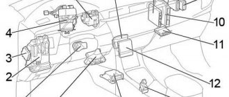
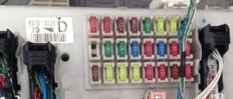
In the cabin
Component location. 1 - block at the top of the center console 2 - block at the end of the dashboard.
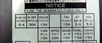
| Decoding the fuses in the cabin blocks | ||
| ||
| ||
| № | Description | Current, A |
| a | Output circuit AM1 of the ignition switch (terminals ACC, IG1, ST1) | 40 |
| b | POWER (windows, sunroof and central locking) | 30 |
| c | DEF (rear window defogger) | 30 |
| 1 | brake lights | 15 |
| 2 | dimensions | 10 |
| 3 | — | |
| 4 | ECU-IG (transmission electronics. ABS, control system lock (automatic transmission) | 15 |
| 5 | windscreen wipers | 20 |
| 6 | ST starting system | 7,5 |
| 7 | IGN ignition | 7,5 |
| 8 | CIG&RAD (carina cigarette lighter fuse, radio, clock, antenna) | 15 |
| 9 | turn signals | 10 |
| 10 | ECU-B (ABC. power supply for central locking) | 15 |
| 11 | instrument lighting, glove box lighting | 7.5 |
| 12 | rear window defroster | 30 |
| 13 | GAUGE devices | 10 |
| 14 | SEAT HTR (seat heater) | 20 |
| 15 | MIR HTR (mirror heater) | 10 |
| 16 | FUEL HTR (fuel heater) | 20 |
| 17 | FR DEF L/UP (increases idle speed when the windshield defroster is turned on) | 15 |
| 18 | RR DEF L/UP (increasing idle speed when turning on the rear window defroster) | 7.5 |
| 19 | FR FOG (fog lights) | 15 |
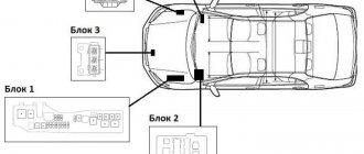
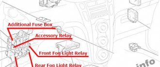
In the engine compartment
Component location. 3 - main mounting block. 4 - relay block No. 4, 5 • relay and fuse block No. 5
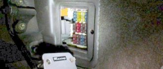
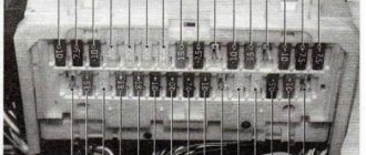
Photo is an example of the main block.
| Diagram of elements in the main engine block of Karina E | ||
| Engine Series S | ||
| A series engines | ||
| № | Decoding | Current, A |
| Circuit breakers | ||
| a | HTR (heater) | 50 |
| b | MAIN (main fuse link) | 40 |
| c | CDS (condenser fan) | 30 |
| d | HDI (air conditioner radiator fan) | 30 |
| 1 | HEAD RH* (right headlight) | 15 |
| 2 | HEAD LH* (singing headlight) | 15 |
| 3 | EFI (injection system) | 15 |
| 4 | reserve | — |
| 5 | — | |
| 6 | HAZARD (Hazard Alarm) | 15 |
| 7 | sound signal (beep) | 10 |
| 8 | — | |
| Relay | ||
| A | STARTER | |
| B | HEATER | |
| C | EFI MAIN | |
| D | ENGINE MAIN | |
| E | HEAD | |
| F | HORN | |
| G | FAN №1 | |
| C series engines | ||
| Circuit breakers | ||
| a | CDS condenser fan | 30 |
| b | RDI air conditioner radiator fan | 30 |
| c | MAIN main insert fuse | 40 |
| d | HTR heating | 50 |
| 1 | — | |
| 2 | HEAD LH* (singing headlight) | 15 |
| 3 | HORN (horn) | 10 |
| 4 | — | |
| 5 | HEAD RН (right headlight) | 15 |
| 6 | alarm | 15 |
| Relay | ||
| A | ENGINE MAIN | |
| B | FAN №1 | |
| C | HEAD | |
| D | STARTER | |
| E | HORN | |
| F | HEATER | |
| * on some modifications, separate fuses for low and high beam headlights are possible, located in fuse block No. 7 | ||
| Relay block No. 4 | |
| A | A/C FAN No. 2 |
| B | A/C FAN No. 3 |
| C | A/C MG CLT |
Toyota Carina PDF Manual - electrical diagrams
Toyota Carina Service Manual
Toyota Carina wiring diagram
Toyota Carina from 1996-2001 Release
Electrical circuits
- Energy distribution
- Starting and ignition system
- Engine management system
- Navigation system
- Electronic automatic transmission control
- Anti-lock braking system
- Electric fan drive
- Power mirrors
- Airbags
- Power windows and mirrors
- Detergents and cleaning products
- Instrument cluster
- Audio system
- Headlights
- Direction indicators and alarm
- Automatic lighting control system
- Air conditioning with manual and automatic control
- central locking
- Analogue instrument cluster and OPTITRON
.
Toyota Carina car diagrams
1. Power distribution (models produced before 08.1998) 2. Toyota Carina starting and ignition control unit (modifications before 08.1998) 3. Battery charging Overdrive (except for models with electronic control) 4. Diagrams of the power unit control system (cars with a 5A-FE engine up to 08.1998) 5. (continued) - Motor control diagram (cars with a 5A-FE engine up to 08.1998) - Navigation (models produced before 08.1998) 6. Schemes control of the Toyota Carina power unit (cars with engines 4A-GE and 7A-FE until 08.1998) 7. Electrical circuit for control. engine (4A-GE and 7A-FE until 08.1998) 8. Toyota Carina power unit control unit (3S-FE until 08.1998) 9. (continued) - Electrical circuit control. engine (3S-FE produced before 08.1998) - Shift lock
10. Automatic transmission control unit (car with 3S-FE engine until 08.1998) 11. Anti-lock braking system (ABS) (until 08.1998) 12. — Electric fan drive (200 W until 08.1998) — Electric fan drive ( models except 200 W until 08.1998) 13. — Electric mirror drive — Airbags (until 08.1998) 14. — Diagram of electric window drive (modifications before 08.1998) — Windshield cleaner and washer 15. — Rear window cleaner and washer — Warning circuits for the key left in the ignition and the lights not turned off — Warning for a seat belt not fastened and loose tension (cars before 08.1998) 16. Dashboard diagrams (until 08.1998) 17. (continued) — Toyota Carina instrument cluster (manufactured before 08.1998) - Cigarette lighter and clock 18. - Toyota Carina audio system (with built-in amplifier until 08.1998) - Audio system (with separate amplifier until 08.1998) 19. - Shift indication - Interior lamps - Reversing lights (cars manufactured before 08.1998)
20. — Headlights — Direction indicators and hazard warning lights 21. — Dimensions — Automatic lighting control circuit (models before 08.1998) — Brake lights 22. Backlight 23. — Fog lights — Horn — Window heaters (before 08.1998) 24. Diagram of an air conditioner with manual control (cars manufactured before 08/1998) 25. Air conditioner with manual control (before 08/1998) 26. — Central locking of Toyota Carina — Ground circuit 27. — Power distribution (from 08/1998) — Connector for connecting additional equipment (since 08.1998) 28. Engine control circuit (cars with ZS-TE 2001 power unit) 29. — Engine control circuit (ZS-TE manufactured since 08.1998) — Electronic control Automatic transmission (model with ZS-TE engine from 08.1998) 30. Engine control (models with 3S-FE power unit from 08.1998) 31. (continued) - Toyota Carina engine control system (3S-FE issue. 2001) - Rear window heater (08.1998, except E Package) 32. Starting and ignition system (models produced from 08.1998) 33. Electronic automatic transmission control (3S-FE from 08.1998) 34. Engine control unit (car models with engines 4A-GE and 7A-FE from 08.1998) 35. Electrical circuit for control. power unit (4A-GE and 7A-FE produced from 08.1998) 36. Diagrams of the automatic transmission electronic control system (4A-GE and 7A-FE vehicles produced from 08.1998) 37. (continued) - Electronic control of the gearbox Automatic transmission Toyota Carina 4A-GE and 7A-FE issue. 2001) - Audio system (with built-in amplifier, manufactured from 08.1998) 38. Engine control system. (vehicles with power unit 5A-FE from 08.1998) 39. — Engine control system (5A-FE from 08.1998) (Continued) — Heated mirrors (08.1998) 40. — Diagram of electric window drive (08.1998) .) - Warning circuits for not fastening a seat belt and loosening the tension (08.1998) 41. - Airbags (08.1998) - Automatic control. lighting (mod. release from 08.1998) 42. Circuits of analog instrument cluster (08.1998) 43. (continued) - Analog instrument cluster (08.1998) - Reversing lights (08.1998) 44. Optitron instrument cluster ( 08.1998) 45. — Instrument cluster Optitron Toyota Carina (2001 models) — Rear window defroster (08.1998, E Package) 46. Manual air conditioning (08.1998) 47. (continued) — Manual air conditioning control Toyota Carina (08.1998) - Electric fan drive (08.1998) 48. Air conditioning with automatic control (model 2001) 49. - Air conditioning with automatic control (08.1998) - Anti-lock braking system (ABS) unit ) (08.1998) 50. Electronic control circuit for automatic transmission (4A-GE and 7A-FE until 08.1998)
Toyota Service Manuals - electrical diagrams
- Prerequisites for a field journal
- Define your corporate philosophy and start living it
- Creating lean processes throughout the enterprise
- Creating initial process stability
- Create associated process
- Establishing standardized processes and procedures
- Leveling up: be more like a tortoise than a hare
- Create a culture that lets you fix problems
- Make technology compatible with people and lean processes
- Develop leaders who live your system and
- Culture from top to bottom
- Develop exceptional team members
- Developing suppliers and partners as extensions
- enterprises
- Solving problems the Toyota way
- Develop Deep Understanding
- Situation and problem definition
- Complete a thorough root cause analysis
- Consider alternative solutions when reaching consensus
- Plan-Do-Check-Act
- Tell a story with an A3 report
- Lean Implementation Strategies and Tactics
Toyota Avalon service manual Free download
Toyota Avalon 2018
Toyota Chaser service manual Free download
Toyota Chaser 1988, 1989, 1990
Toyota HIACE repair manual Free download
Toyota Hiace
Toyota Echo Service manual Free download
Toyota Echo 2002
Toyota Celica Service manual Free download
Toyota Celica 2000.
Electrical diagrams TOYOTA AVENSIS - Car electrical wiring diagram
Electrical connection diagram TOYOTA AVENSIS
TOYOTA AVENSIS brake light connection diagram
TOYOTA AVENSIS - Starting diagram
TOYOTA AVENSIS charger connection diagram
Connection diagram for the TOYOTA AVENSIS ignition system
TOYOTA AVENSIS engine control wiring diagram
Connection diagram for door lock control system and anti-theft system TOYOTA AVENSIS
TOYOTA AVENSIS wiring diagrams are above the page.
The Toyota Avensis replaced the Carina in 1997. Production of first generation cars continued until 2003.
The Avensis came in sedan, hatchback and estate versions (which was a separate Caldina ). For the car there were three petrol engines 1.6, 1.8 and 2.0, as well as a two-liter turbodiesel.
The second generation Toyota Avensis (2003-2008), as before, was produced with the same body types at a plant in the UK, from where the cars were delivered, including to the Japanese market.
Avensis sedans and station wagons were sold in 1.8 L (129 hp), 2.0 L (147 hp) and 2.4 L and 163 hp. In Europe, in addition, there were versions with a 1.6-liter engine. gasoline engine and with diesel engines 2 and 2.2 liters. Japanese buyers were offered cars with 2.0 or 2.4 gasoline engines, including all-wheel drive.
.
Fuses and relays Toyota Carina (T210), 1996 - 2001
Most of the power supply circuits of the electrical equipment of the Japanese sedan are protected by fuses. Headlights, electric fan motors, fuel pump and other powerful current consumers are connected through a relay. Protective elements are installed in mounting blocks, which are located under the hood and in the passenger compartment.
The fuse diagrams are relevant for Toyota Carina (T210) cars 1996, 1997, 1998, 1999, 2000, 2001 with gasoline engines 4A-GE (16L), 5A-FE (1.5L), 7A-FE (1.8L) , 3S-FE (2.0l).
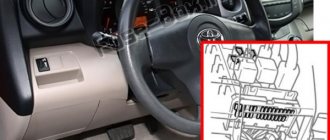
In the cabin
The mounting block is located on the driver's side behind a plastic cover.
| Interior fuse box diagram | ||
| № | Decoding | Current, A |
| 1 | Idle speed boost system, electronic engine control unit | 5 |
| 2 | Rear window defroster | 30 |
| 3 | Anti-lock braking system ABS, gear shift lock system | 15 |
| 4 | Front and rear lights, license plate lights | 10 |
| 5 | Electronic engine control unit START FR | 5 |
| 6 | Electronic engine control unit IGNITION | 5 |
| 7 | Direction indicators | 10 |
| 8 | Windshield wipers and washers | 20 |
| 9 | Instrument cluster | 15 |
| 10 | Illumination of the instrument cluster and switches | 7,5 |
| 11 | Electric side mirrors, carina cigarette lighter fuse, clock, radio | 15 |
| 12 | Front fog lights | 15 |
| 13 | central locking | 30 |
| 14 | Brake lights | 15 |
Component location. 13 — electronic engine control unit, 14 — door lock control relay, 15 — integrated relay (models from 08-1998), 16 — mirror heater relay (models from 08/1998), 17 — relay block No. 1, 18 — connector holder, 19 — mounting block under the instrument panel, 20 — brush deicer relay, 21 — central mounting block, 22 — locking control unit, 23 — SRS electronic control unit, 24 — deceleration sensor, 25 — fuel pump relay (models before 08.1998 26 — heater relay (models from 08/1998), 27 — fuel pump relay (models from 08/1998), 28 — ABS electronic control unit (models before 08/1998)
| under-dash mounting block |
| central mounting block |
| relay block No. 1 |
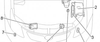
In the engine compartment
It is located on the right side, near the battery. It is closed with a plastic cover.
Photo is an example of execution.
| Fuse diagram of the engine block Karina 210 | ||
| № | Current, A | Description |
| 1 | 15 | EFI Electronic Engine Control Module |
| 2 | 10 | Sound signal |
| 3 | 5 | Generator ALT-S |
| 4 | 7,5 | Interior lighting, trunk lighting, clock |
| 5 | 15 | Left headlight |
| 6 | 15 | Right headlight |
| 7 | 10 | Alarm |
| 8 | 30 | Ignition switch AM2 |
| 9 | 15 | Radio tape recorder |
| 10 | 5 | ECU-B: Airbag System (SRS), Anti-Lock Brake System |
Component location. 1 — absolute pressure sensor in the intake manifold, 2 — electronic control unit ABS and pressure modulator (models from 08.1998), 3 — glow plug relay (diesel), 4 — mounting block No. 2, 5 — fuse block, 6 — front left SRS sensor (models from 08.1998), 7 - relay block No. 5 (models before 08.1998), 8 - front right SRS sensor (models from 08.1998), 9 - boost pressure sensor (diesel), 29 — relay block No. 2
| mounting block No. 2, fuse block, relay block No. 2 |
| until 08.1998 |
| from 08.1998 |
Body
Component location. 10 — navigation system (GPS) receiver (models from 08/1998), 11 — audio system amplifier (models before 08/1998), 12 — TV tuner (models from 08/1998), 30 — rear window wiper relay.